The ratio of er to eg in the red light flux in the wavelength range of 630nm~660nm is 0.9; The ratio of blue light flux φ eb to eg in the wavelength range of 435nm to 465nm is 0.9;
4. Output total luminous flux: 4800-1050lm;
5. Optical output aperture: 016/20+0.050mm;
6. Security type: Class 1, BF type application part;
7. Dimensions: 320mm (length) x 300mm (width) x 130mm (height);
8. Weight: 9Kg.
9. Environmental conditions for use
Atmospheric pressure: 860hPa~1060hPa.
1. Symbol Explanation
In this user manual, use the following symbols.
Danger indicates extreme danger. If not avoided, it can lead to unnecessary serious injuries.
Warning indicates potential harm. If not avoided, it may cause unnecessary moderate harm.
Attention indicates potential harm. If not avoided, it can cause mild symptoms. Also used to alert unsafe operations or potential equipment damage
Bad.
Explanation of specific matters.
2. Illustration Explanation
Strictly follow the following preventive measures, otherwise it may cause the operator to suffer electric shock.
2. All electrical equipment should be kept away from liquids. If any liquid splashes into the equipment, stop using it immediately and contact our after-sales service department.
3. When preparing, inspecting, or using this light source, users should ensure that their hands are dry and not damp.
Do not install or use this light source in the following places, otherwise it may cause explosions or fires due to the lack of explosion-proof function of cold light sources.
a、 Places with high oxygen concentration;
b、 Places where flammable gases exist;
c、 In a high magnetic field environment.
Warning: Please do not violate the following requirements to ensure the safety of use
1. Do not touch the output port of the optical cable when it is removed from the light source output hole to avoid being burned by high heat.
2. Please do not look directly at the cold light source light output hole and fiber optic cable output port (fiber optic emitting end) with the naked eye when checking the illumination light, in order to avoid eye burns or discomfort or injury to the eyes.
3. Due to the high-intensity light required for catalytic operation, the light source generates a large amount of heat. Do not let the fiber optic cable output port or the front end of the light source output head come into contact with the cover cloth or other flammable materials.
4. Turn off the power promptly when the cold light source is not in use.
To prevent any abnormal situations with the equipment, please prepare another cold light source for emergency use.
Attention ● Please do not ignore the following reminders:
1. Do not touch the switch on the front panel with sharp or hard objects, as it may damage the switch.
2. Do not touch the output light hole of the cold light source to avoid burns.
3. Do not apply excessive force to each connection.
4. Cold light sources should not vibrate violently, and should be handled with care when moving.
5. When the cold light source is working, it should be kept at least 15cm away from the wall, and no other items should be placed on the chassis.
6. After using the light source, the chassis should be placed in a ventilated and dry place, and after cooling in standby mode, a dust cover should be added for storage.
7. The light source chassis should have good grounding performance, and reliable grounding wires should be connected to the grounding pins on the power supply wiring board.
8. To avoid interference with other research electrical equipment used in the vicinity and prevent electromagnetic interference from other devices during work, the power cord should be separately connected to the power supply.
9. When the components and equipment replaced from the light source reach the end of their service life and are scrapped, they should be handed over to professional waste recycling institutions or qualified solid waste disposal units for disposal. Do not dispose of them without authorization to reduce secondary pollution and other risks. 6、 Usage method
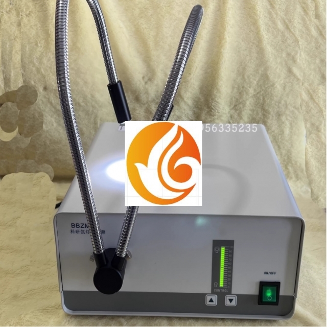
When using, the light source should be placed in an environment far away from high magnetic fields. Check if the protective grounding of the middle pole of the three core power socket is reliable. Insert one end of the power cord in the attachment into the power socket behind the light source chassis, and connect the other end to the network power supply. The cold light source operation panel is shown in Figure 1:
1. Model Description
2. Light output hole
3. Light intensity indicator button
4. Power switch
5. Brightness adjustment button (top)
6. Brightness adjustment button (below)
Figure 1 Front of the host
1. Insert one end of the optical cable into the xenon lamp light output hole (2), turn on the power switch (4), and the xenon lamp will start working.
2. The brightness of the xenon lamp can be adjusted by pressing the adjustment button (5/6) to change its size. Brightness increases, brightness decreases. The brightness indicator (3) displays the brightness status.
Behind the cold light source, as shown in Figure 2:
1. Product nameplate 2, fan cooling hole (inlet)
3. Protective grounding terminal
4. Fan cooling hole (air outlet) 5, power cord socket
Figure 2: Behind the Host
1. Insert one end of the power cord into the power cord socket on the back of the light source chassis (5), and connect the three core plug end to the network power supply.
2. Fuse holder (5): Install F5AL250V, Φ 5 × 20 fuse.
3. Connect the protective grounding terminal (3) to the grounding wire.